
Press MENU key, and instrument will entry to menu mode. In this mode, you can set and check.
$11 10.1 Remote Height Measurement (REM)
This program is for measuring the vertical distance (height) between remote target and prism and the height between it and the ground (no-prism height). When prism is used, the prism shall be used as the datum point for REM; while the ground point of the measured vertical angle shall be used as the datum point for measuring when no prism is used. The datum points of both above cases are located on the plumb line of the target point.
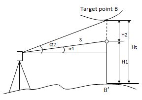
Here is the equation used to calculate the data presented in above figure:
Ht=H1+ S*cosα1*tgα2-S*sinα1
H2= S*cosα1*tgα2-S*sinα1
10.1.1 Ground to target
|
Operation Steps |
Key |
Display |
||||||||||||||
|
1) Press [MENU] and then [4](Programs) to enter into PROGRAMS function |
[MENU] [4] |
|
|
2) Press [1](REM(Height Meas)). |
[1] |
|
||||||||||||||||||||||||||||||||||||||||||||||||||||||||
|
3) select menu item [1](Ground to target) when you need the height between the target and ground. |
[1] |
|
||||||||||||||||||||||||||||||||||||||||||||||||||||||||
|
4) Setting height of instrument and the height of prism. |
Set instrument and prism height |
|
||||||||||||||||||||||||||||||||||||||||||||||||||||||||
|
[F1] |
|
||||||||||||||||||||||||||||||||||||||||||||||||||||||||
|
6) Press [F4](ENTER) to accept the measurement data |
[F4] |
|
||||||||||||||||||||||||||||||||||||||||||||||||||||||||
|
then VD(difference of height) appear ,first display the height of prism |
||||||||||||||||||||||||||||||||||||||||||||||||||||||||||
|
7) If you rotate the telescope then VD will change, when you aim at the target the VD is the difference of height between the target and ground |
|
|||||||||||||||||||||||||||||
10.1.2 Point to point
|
Operation Steps |
Key |
Display |
||||||||||||||||||||||||||||
|
1) Press [MENU] and then [4](Programs) to enter into PROGRAMS function window. |
[MENU] [4] |
|
||||||||||||||||||||||||||||
|
2) Press [1](REM(Height Meas)). |
[1] |
|
||||||||||||||||||||||||||||
|
3) Select menu item [2](Point to point) when you need the difference of height between any two points. |
[2] |
|
||||||||||||||||||||||||||||
|
4) Press [F1] (Meas) to start EDM then you can obtain the horizontal distance between the instrument and the target. |
[F1] |
|
||||||||||||||||||||||||||||
|
6) Press [F4](ENTER) to accept the measurement data |
[F4] |
|
||||||||||||||||||||||||||||||||
|
Then VD(difference of height) will change when you rotate telescope |
||||||||||||||||||||||||||||||||||
|
7) If you rotate the telescope then VD will change, when you aim at the target the VD is the difference of height between the target and ground |
|
|||||||||||||||||||||||||||||||||
$11 10.2 Missing line measurement (MLM)
With this mode, the horizontal distance (dHD), slope distance (dSD), and height difference (dVD) between two prisms can be measured.
MLM mode has two functions
(A-B, A-C): measuring A-B, A-C, A-D…
(A-B, B-C): measuring A-B, B-C, C-D…
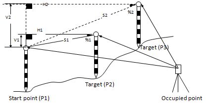
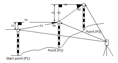
The measuring process of MLM-2 (A-B,B-C) mode is totally the same as MLM-1 mode.
|
Operation Steps |
Key |
Display |
||||||||||||||
|
1) Press [MENU] and then [4](Programs) to enter into PROGRAMS function. |
[MENU] [4] |
|
||||||||||||||
|
Select as desired [1] or [2] |
|
||||||||||||||
|
3) Select one of two models. |
Select as desired [1] or [2] |
|
|
Collimate A [F1] |
|
||||||||||||||||||||||||||||
|
[F1] |
|
||||||||||||||||||||||||||||
|
6) Press [ENTER] to accept the measurement data. The system will remind you to implement measurement of the second point. |
[ENT] |
|
||||||||||||||||||||||||||||
|
[F1] |
|
||||||||||||||||||||||||||||
|
6) System calculates dSD, dHD and dVD between prism A and prism B according to the positions of points A and B. |
|
|||||||||||||||||||||||||||||
|
7) Press F1(NEXT) to measure distance between A‐C |
||||||||||||||||||||||||||||||
$11 10.3 Setting Z coordinate of occupied point
Occupied point coordinates data and known point actual measuring data are used to calculate Z coordinate.
Coordinate data file can be used as Known point data and coordinate data.
Only Z (elevation) of an instrument station is determined by this measurement
|
Operation Steps |
Key |
Display |
|||||||||||||||||||||||||||||||||||||||||||||||||
|
1) Press [MENU] and then [4](Programs) to enter into PROGRAMS function |
[MENU] [4] |
|
|||||||||||||||||||||||||||||||||||||||||||||||||
|
[3] |
|
|||||||||||||||||||||||||||||||||||||||||||||||||
|
3) Press ENT to setup Station. |
[ENT] |
|
|||||||||||||||||||||||||||||||||||||||||||||||||
|
4) Press [F1](Input) to enter coordinates of the occupied point. |
[F1] |
|
|||||||||||||||||||||||||||||||||||||||||||||||||
|
5) Input point name and coordinate N and press [F4] (Enter) to enter the next value. Input the coordinate E and Z with the same method. |
Input coordinates |
|
|||||||||||||||||||||||||||||||||||||||||||||||||
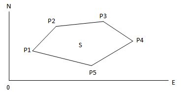
10.4 Area
Calculate an area shaped with several points. The coordinate data of the points could be either measured or input by hand.
NOTE:
$1· The number of points: 3 ~ 20.
$1· Make sure these points must be measured or listed clockwise or anticlockwise, or mistake will result.
10.4.1 Area calculation from measured data
|
Operation Steps |
Key |
Display |
||||||||||||||||||||||||||||
|
1) Press [MENU] and then [4](Programs) to enter into PROGRAMS function. |
[MENU] [4] |
|
||||||||||||||||||||||||||||
|
[4] |
|
||||||||||||||||||||||||||||
|
3) Press [F2](Meas) |
[F2] |
|
|||||||||||||||||||||||||||||||||
|
4) You will see the coordinates of the target points, press [F4](Enter) to continue. |
[F4] |
|
|||||||||||||||||||||||||||||||||
|
5) The system will return to Survey area mean menu, with the new point saved in the list |
|
||||||||||||||||||||||||||||||||||
|
6) Repeat steps 3 ~ 5 until you have at least three points. After the numbers of points is more than 3, the calculation is possible. |
|
||||||||||||||||||||||||||||||||||
|
7) Press [F4] (Calc). The Area and Perimeter of the shape is surrounded by the points in list box. |
[F4] |
|
|||||||||||||||||||||||||||||||||
10.4.2 Area calculation from Coordinate data file
|
Operation Steps |
Key |
Display |
||||||||||||||||||||||||||||||||
|
1) Press [MENU] and then [4] (Programs) to enter into PROGRAMS function. |
[MENU] [4] |
|
||||||||||||||||||||||||||||||||
|
[4] |
|
||||||||||||||||||||||||||||||||
|
3) Press [F1](Input) |
[ENT] |
|
||||||||||||||||||||||||||||||||
|
4) You will see the coordinates of the target points, press [F4](Enter) to continue |
[F4] |
|
||||||||||||||||||||||||||||||||
|
5) The system will return to Survey area mean menu, with the new point saved in the list |
|
|||||||||||||||||||||||||||||||||
|
6) Repeat steps 3 ~ 5 until you have at least three points. After the numbers of points is more than 3, the calculation is possible. |
Input coordinates |
|
|||||||||||||||||||||||||||||||||
|
7) Press [F4] (Calc). The Area and Perimeter of the shape is surrounded by the points in list box. |
[F4] |
|
|||||||||||||||||||||||||||||||||
10.5 Roadway
Roadway application program is composed of designing and roadway setout. When you select roadway function then the menu is appeared as follow:
|
-- Roadway— |
|
|
1. Open Road File |
▲ |
|
2. New H Curve file |
|
|
3. New V Curve file |
|
|
4. Resume H curve |
|
|
5. Resume V curve |
|
|
6. Road Setout |
▼ |
10.5.1 Define the Horizontal Curve of Roadway
Horizontal alignment data can be edited manually or encased from computer. Horizontal alignment consisted of following elements: starting point, straight line, circular curve, spiral and point of intersection
Straight line
When the start point or other line style is well‐defined, it allows you to define straight line. A straight line consists of bearing angle (AZ) and distance; the distance value cannot be minus
|
Operation Steps |
Key |
Display |
||||||||||||||||||||||||||||||||
|
1) Press [MENU] and then [4] to enter PROGRAMS menu
|
[MENU] [4] |
|
||||||||||||||||||||||||||||||||
|
2) Press[6](Roads) |
[6] |
|
||||||||||||||||||||||||||||||||
|
3) Press [2](New H curve file) to define horizontal element |
[2] |
|
||||||||||||||||||||||||||||||||
|
4) Select the method of element to define horizontal roadway. Press [F1](Line) first |
[F1] |
|
||||||||||||||||||||||||||||||||||||||||||||||||||||||||||||||||
|
5) Input the Mileage and coordinates of start point |
Input Mileage and coordinates |
|
||||||||||||||||||||||||||||||||||||||||||||||||||||||||||||||||
|
6) Press [ENT] to confirm. |
[ENT] |
|
||||||||||||||||||||||||||||||||||||||||||||||||||||||||||||||||
|
Press [F1](Line) |
[F1] |
|
||||||||||||||||||||||||||||||||||||||||||||||||||||||||||||||||
|
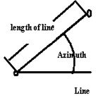
8) Input the start azimuth and the length of line |
Input azimuth and length of line |
|
||||||||||||||||||||||||||||||||||||||||||||||||||||||||||||||||
|
9) System automatically calculates the mileage and azimuth of the fan-out-point |
|
|||||||||||||||||||||||||||||||||
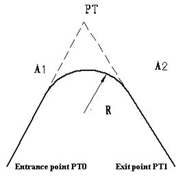
Circular Curve
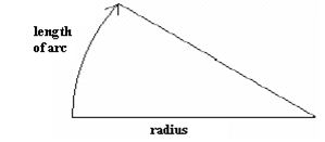
Press [Circle] in the “Main line Input Screen”, the circular curve can be defined. Circular curve consists of Arc length and Radius. The rule of radius value: along the forward direction of the curve. When the curve rotates to right, the radius value is positive. When the curve rotates to left, the radius value is minus. The arc length cannot be minus.
|
Operation Steps |
Key |
Display |
||||||||||||||||||||||||||||||||||||||||||||||||||||||||||||||||
|
1) Press [F2](Circle), the screen of defining circle will be shown. |
[F2] |
|
||||||||||||||||||||||||||||||||||||||||||||||||||||||||||||||||
|
2) Input radius and arc length, then press [ENT] to save. |
Input Radius and arc length [ENT] |
|
||||||||||||||||||||||||||||||||||||||||||||||||||||||||||||||||
|
|
|||||||||||||||||||||||||||||||||
Spiral
Press [F3] (Spiral) in the Main Line Input Screen, the transition curve can be defined. Transition curve consists of the minimum radius and arc length. The rule of radius value: along the forward direction of the curve. When the curve rotates to right, the radius value is positive. When the curve rotates to left, the radius value is minus. The arc length cannot be minus
|
Operation Steps |
Key |
Display |
||||||||||||||||||||||||||||||||||||||||||||||||||||||||||||||||
|
1) Press [F3](Spiral), in the screen of defining circle will be shown. |
[F3] |
|
||||||||||||||||||||||||||||||||||||||||||||||||||||||||||||||||
|
2) Input radius and arc length, then press [ENT] to save. |
Input Radius and arc length [ENT] |
|
||||||||||||||||||||||||||||||||||||||||||||||||||||||||||||||||
|
|
|||||||||||||||||||||||||||||||||
Max number of element is 20. Press [ENT] to pop up the list box of all inputted elements. Press [F1] (Save) to save all elements to current file and quit defining. Press [F2] (View) to browse the detailed information of an element, or to edit it.
|
List (H element) |
|||
|
01Begin |
100.000 |
||
|
02line |
100.000 |
||
|
03circle |
150.000 |
||
|
04spline |
170.000 |
||
|
Save |
View |
Add |
|
10.5.2 Procedure of defining Horizontal point of intersection
|
Operation Steps |
Key |
Display |
|
1) Press [2](New file curve H), in the screen of menu roadway. |
[2] |
Curve define(H) Mileage: 0.000 Azimuth: 0°00’00”
Line Circle Spiral I.P.
|
|
[F4 (I.P)] |
Define(H)-Begin
Mileage: 1000 N: 10 E: 20 B.S. Clear Enter
|
$
|
N:(Pt.1) 100 E: 100 Radius: 50 A1: 20 A2: 20 B.S. Clear Enter |
|
|
Press F2:[View] to browse the detailed information of an I.P.,or to edit it. |
List(H element) 01Begin: 100 02I.P.: 150 03I.P.: 170 04I.P.: 215 Save View Add |
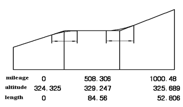
10.5.3 Defining the Vertical Curve of Roadway
The specialty of the roadway slope should be described by the vertical curve, there are three attributes on the vertical curve—mileage, altitude and length, the mileage is representative of the point where the slope is changed, the altitude is the altitude of the point where the slope is changed, the length indicate how much curve length is designed to implement the slope changing. The figure is shown as follow.
The input method of defining vertical curve is just same as the horizontal I.P., see (Procedure of defining Horizontal point of intersection).
10.5.3 Roadway setout
When you select road-setout function, a menu named “road setout” is popped up. Before setout, you should do something:
1. load a LINE-TYPE file from file to memory using menu item
2. if you have defined a roadway just now then you cannot do it;
3. the coordinates of instrument station must be setup, you can use menu item 2
4. The azimuth must be setup, you can use menu item 3.
—Pt. project—
1.Select file
2.Setup ST
3.Setup BSS
4.Road Setout
The figure for road setout is shown as follow:
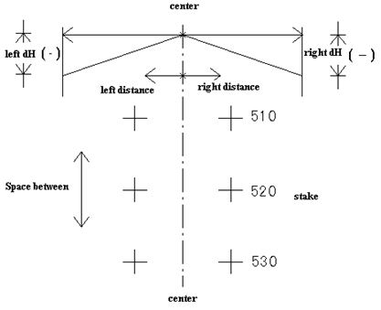
Procedure of road setout
|
1) Input the start mile and space between |
[4] |
Roadsetout-Parameter 1/2 Start Mile: 100 Space Between 10 B.S. Clear Enter |
|
Roadsetout-para 2/2 Leftdist: 10 Rightdist: 10 Left dH: 0.1 Right dH: 0.1 B.S. Clear Enter |
|
|
You can press F1:[Edit] to input the mile. Then you can press F3:[Setout] |
Roadsetout-Right edge Mile: 100.00 Offset: 10.00 dH: 0.100 T.H.: 1.000
|
|
4) The coordinate of the position on the stake is calculated, in this time you can press |
F2:[Rec] to save the coordinates. Press F4:[Enter] to setout. |
Pt.name 100.0 Code: N: 1.000 E: 11.000 Z: 0.000 Rec Enter
|
|
You can press F1:[Dist] or F2:[Coor.] to setout. |
Roadsetout - Calc HR: 84°48’20” HD: 11.045 |
Press F4:[Next] to setout the next stake.
|
Press F4:[Next] to setout the next stake. |
HR: 24°32’20” dHR: -60°16’00” HD: dHD: m dZ: |