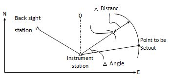
Setout measurement is used to Setout the required point. The difference between the previously inputted data to the instrument(the Setout data)and the measured value can be displayed by measuring the horizontal angle, distance or coordinates of the sighted point.
The horizontal angle difference and distance difference are calculated and displayed using the following formulas:
Horizontal angle difference
dHA =Horizontal angle of Setout data – measured horizontal angle
Distance difference
Distance Displayed item
SD: S-O SD=measured slope distance – slope distance of Setout data
HD: S-O HD=measured horizontal distance – horizontal distance of Setout data
VD: S-O VD=measured height difference – height difference of Setout data
There are the following steps:
1. Setting occupied point.
2. Setting backsight point and azimuth angle.
3. Input layout point coordinates, and then starts.
NOTE:
$1· Setout data can be input in various modes: SD, HD, VD, coordinates and REM measurement.
$1· EDM settings could be set in this mode.
$11 8.1 Preparation
Setting the Grid Scale
Calculation Formula
1)Elevation factor
Elevation factor=R/(R+ELEV)
R:The average radius of the earth
ELEV:The elevation above the mean sea level
2)Scale factor:
Scale factor in the surveying station
3)Grid factor
Grid factor = Elevation factor×Scale factor
Distance calculation
1)Grid distance
HDg=HD×Grid factor
HDg:Grid distance
HD:Ground distance
2)Ground distance
HD= HDg/ Grid factor
|
Operation Steps |
Key |
Display |
||||||||||||||||||||||||||||||||||||||||||||||||||||||||||||||||
|
Press Menu, and then press [2](Setout). |
|
|||||||||||||||||||||||||||||||||||||||||||||||||||||||||||||||||
|
2) In Setout menu, press [7](Grid Scale) |
[7] |
|
||||||||||||||||||||||||||||||||||||||||||||||||||||||||||||||||
|
2)input Elevation, press [F4](ENT) |
Input Elevation [F4] |
|
||||||||||||||||||||||||||||||||||||||||||||||||||||||||||||||||
|
)Input Scale Factor in the same way, press [F4](ENT) |
Input Scale Factor [F4] |
|
||||||||||||||||||||||||||||||||||||||||||||||||||||||||||||||||
$11 8.2 Coordinates Setout Measurement
After setting coordinates for the point to be Setout, the instrument calculates the Setout HA and HD. By selecting the HA and then the HD Setout functions, the required coordinate location can be Setout.
To get the Z coordinate, attach the target to a pole etc, with the same target height
The following methods can be selected to launch a Setout:
$1· Direct input of coordinates values
· Obtaining points from internal memory by point number
8.2.1 Direct input of coordinate values
|
Operation Steps |
Key |
Display |
||||||||||||||||||||||||||||||||||||||||||||||||||||||||||||||||
|
1) Press Menu, and then press [2] (Setout). |
[Menu] [2] |
|
||||||||||||||||||||||||||||||||||||||||||||||||||||||||||||||||
|
2) In Setout Menu, press [3](Setout) |
[3] |
|
||||||||||||||||||||||||||||||||||||||||||||||||||||||||||||||||
|
3) Input point coordinates that you need to setout. |
Input coordinates |
|
||||||||||||||||||||||||||||||||||||||||||||||||||||||||||||||||
|
4) Press [ENT], The system calculates out the angle that the lens should be rotated, horizontal distance HD, then you can select one of two setout mode – distance or coordinate |
|
|||||||||||||||||||||||||||||||||||||||||||||||||||||||||||||||||
|
[F2] |
|
||||||||||||||||||||||||||||||||||||||||||||||||||||||||||||||||
|
6) Collimate prism and press [F1] (Meas) to start to measure |
[F1] |
|
||||||||||||||||||||||||||||||||||||||||||||||||||||||||||||||||
|
7) When the display value dHR, dN, dE and dZ are equal to 0,the layout point is established |
|
|||||||||||||||||||||||||||||||||||||||||||||||||||||||||||||||||
|
8) Press [F4] (Next) to set next layout point |
[F4] |
|
||||||||||||||||||||||||||||||||||||||||||||||||||||||||||||||||
|
*Press [F3] (T.H.) to input target height again. |
||||||||||||||||||||||||||||||||||||||||||||||||||||||||||||||||||
8.2.2 Obtaining point from internal memory
|
Operation Steps |
Key |
Display |
||||||||||||||
|
1) Press Menu, and then press [2] (Setout). |
[Menu] [2] |
|
|
2) In Setout Menu, press [3](Setout) |
[3] |
|
||||||||||||||||||||||||||||||||||||||||||||||||||||||||||||||||
|
Input coordinates |
|
||||||||||||||||||||||||||||||||||||||||||||||||||||||||||||||||
|
[ENT] |
|
||||||||||||||||||||||||||||||||||||||||||||||||||||||||||||||||
|
[▲] or [▼] [F4] |
|
||||||||||||||||||||||||||||||||||||||||||||||||||||||||||||||||
|
6) Press [ENT], The system calculates out the angle that the lens should be rotated, horizontal distance HD, then you can select one of two setout mode – distance or coordinate |
[ENT] |
|
||||||||||||||||||||||||||||||||||||||||||||||||||||||||||||||||
|
[F2] |
|
||||||||||||||||||||||||||||||||||||||||||||||||||||||||||||||||
|
8) Collimate prism and press [F1] (Meas) to start to measure |
[F1] |
|
||||||||||||||||||||||||||||||||||||||||||||||||||||||||||||||||
|
9) When the display value dHR, dN, dE and dZ are equal to 0,the layout point is established |
|
|||||||||||||||||||||||||||||||||||||||||||||||||||||||||||||||||
|
10) Press [F4] (Next) to set next layout point |
[F4] |
|
||||||||||||||||||||||||||||||||||||||||||||||||||||||||||||||||
|
*Press [F3] (T.H.) to input target height again. |
||||||||||||||||||||||||||||||||||||||||||||||||||||||||||||||||||
$11 8.3 Intersection
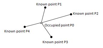
Intersection program is used to determine the coordinates of an instrument station (unknown) by measuring several known points. Coordinate data in memory could be read.
Coordinates of known points: Xi, Yi, Zi
Measured HA: Hi
Measured VA: Vi
Measured distance: Di
Output
Coordinate of occupied data: Xo, Yo, Zo
Note:
$1· All N, E, Z value or only Z value of the occupied point is calculated by measuring known points.
$1· Coordinate intersection measurement overwrites the N, E, Z data of the instrument station.
$1· Inputted known coordinate data and calculated data could be recorded in the current coordinate file.
$1· Max number of known points is 5
8.3.1 Coordinate Intersection
|
Operation Steps |
Key |
Display |
||||||||||||||
|
1) Press [MENU], and then press [2] (Setout). |
[Menu] [2] |
|
|
2) In Setout Menu, press [5](Intersection) |
[5] |
|
||||||||||||||||||||||||||||||||||||||||||||||||||||||||||||||||
|
Input coordinates |
|
||||||||||||||||||||||||||||||||||||||||||||||||||||||||||||||||
|
[F4] |
|
||||||||||||||||||||||||||||||||||||||||||||||||||||||||||||||||
|
[▲] or [▼] [F4] |
|
||||||||||||||||||||||||||||||||||||||||||||||||||||||||||||||||
|
6) Press [F1] (Input), to change the prism height and the instrument height. Press [ENT] to confirm. |
[F1] [ENT] |
|
||||||||||||||||||||||||||||||||||||||||||||||||||||||||||||||||
|
7) Press [ENT]. Then you can select one of two setout mode – distance or angle |
|
|||||||||||||||||||||||||||||
Collimate the prism and press [F4] (Dist). |
Collimate prism [F4] |
|
||||||||||||||||||||||||||||
|
9) EDM will start and obtaining the slope distance. After measuring distance, press [F1](Next) to measure the next point. |
[F1] |
|
||||||||||||||||||||||||||||
|
10)Repeat procedure 3 ~ 9 at least one more time* if you have measured two or more distance the prompt “Calc” will appear |
|
|||||||||||||||||||||||||||||
|
11) Press [F4] (Calc) to obtain the coordinates of instrument station. The result of calculated instrument station is shown as the picture on the right. This is the error of the station coordinates |
[F4] |
|
||||||||||||||||||||||||||||
|
[F4] |
|
|||||||||||||||||||||||||||||||||
|
13) Press [F1](SetST) to set this station as actual |
[F1] |
|
||||||||||||||||||||||||||||||||
|
14) Press [F2](SetA) to setup the Azimuth of the instrument. |
[F2] |
|
||||||||||||||||||||||||||||||||
|
15) Press [F3](Rec) to save coordinates to current measurement file |
[F3] |
|
||||||||||||||||||||||||||||||||
|
16)Press ESC to return to Setout menu |
||||||||||||||||||||||||||||||||||
|
*Press [F3] (T.H.) to input target height again. |
||||||||||||||||||||||||||||||||||
8.3.2 Precautions when performing intersection
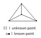
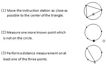
In some cases it is impossible to calculate the coordinates of occupied point if the unknown point and three or more known points are arranged on the edge of a single circle. It is also impossible to calculate if the included angle between the known points is too small. Be careful for the points can easily be aligned on the edge of a single circle.
An arrangement such as shown below is desirable.
It is sometimes impossible to perform a correct calculation such as shown below.
When they are on the edge of a single circle, take one of the following methods:


