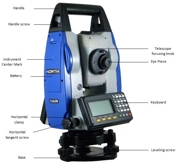
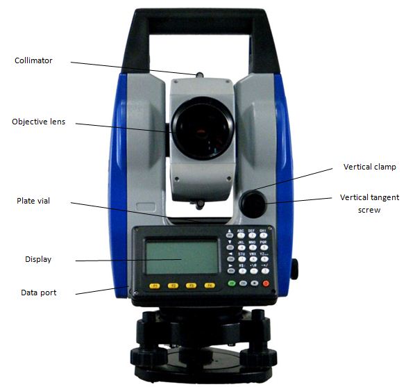
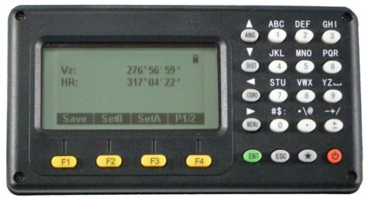
1.1 Nomenclature
1.2 Functions Keys
|
Key |
Name |
Function |
|
F1~F4 |
Soft Keys |
Functions corresponding to information displayed |
|
0~9 |
Number Keys |
1. Input number when numeric input |
|
. |
Decimal point |
Input decimal point |
|
± |
Sign |
Input plus /minus sign |
|
★ |
Star Key |
Enter into setting mode directly |
|
POWER |
Power |
Power ON/OFF |
|
ENT |
Enter |
Confirm End dialog and save setting to file |
|
ESC |
Escape |
Escape to the previous menu or mode; end dialog and not save |
|
ANG |
Angle Measuring |
1. Enter to angle measurement mode |
|
DIST |
Distance Measurement |
1. Enter into distance and angle measurement mode(under basic measurement mode) |
|
CORD |
Coordinate measurement |
1. Enter into coordinate and angle measurement mode(under basic measurement mode) |
|
MENU |
Menu |
1. Enter into menu mode(under basic measurement mode) |
1.3 Display
The LCD could display 7 lines with 24 characters per line. In measurement mode, it displays some common information in above 5 lines and displays soft functions in the last line.
Contrast and Illumination
The contrast and illumination of display window are adjusted. See “1.5 Star key mode” to change contrast level.
Display marks
Symbol Displayed |
Meaning |
|
Vo |
Vertical angle reading from horizontal line clockwise |
|
Vh |
Vertical angle reading from horizontal line anticlockwise |
|
Vz |
Vertical angle reading from zenith |
|
V% |
Vertical Angle (slope percentage) |
|
HR |
Horizontal Angle (right) |
|
HL |
Horizontal Angel (left) |
|
HD |
Horizontal Distance |
|
SD |
Slope Distance |
|
N |
North Coordinate |
|
E |
East coordinate |
|
Z |
Height |
|
* |
EDM (Electronic distance meter) is under operation |
|
m |
Meter as the unit |
|
ft |
Foot as the unit |
|
fi |
Foot and inch as the unit |
1.4 Functional Keys
ANGLE MEASUREMENT MODE
|
|
|
|
|
|||||
|
Vz: |
90°10’20” |
|
|
|||||
|
HR: |
122°09’30” |
|
|
|||||
|
|
|
|
|
|||||
|
|
|
|
|
|||||
|
Save |
Set0 |
SetA |
P1/2 |
|
||||
|
|
Hold |
L/R |
Vmode |
P2/2 |
||||
|
Page |
Soft key |
Display |
Function |
|
Page 1 |
F1 |
Save |
Start angle measurement, and save the results in respective job. (Measurement files and coordinates files are selected in DATA COLLECT menu.) |
|
F2 |
Set0 |
Set horizontal angle to 0 degree. |
|
|
F3 |
SetA |
Input horizontal angle by keyboard |
|
|
F4 |
P1/2 |
Display the soft key functions in Page 2. |
|
|
Page 2 |
F1 |
Hold |
Lock the reading of horizontal angle |
|
F2 |
L/R |
Shift between right/left angle of horizontal angle. |
|
|
F3 |
Vmode |
Shift between vertical angle measurement mode |
|
|
F4 |
P2/2 |
Display the soft key functions on Page 3. |
DISTANCE MEASUREMENT MODE (2 interface menus)
|
V: |
90°10’20” |
|
|
|||||
|
HR: |
122°09’30” |
|
|
|||||
|
SD*[FS] |
<< |
|
|
|||||
|
HD |
|
|
|
|||||
|
VD |
|
|
|
|||||
|
Save |
Meas |
Mode |
P1/2 |
|
||||
|
|
Offset |
Setout |
m/f/i |
P2/2 |
||||
|
Page |
Soft key |
Display |
Function |
|
Page 1 |
F1 |
Save |
Start distance measurement, and save the results in respective job. (Measurement files and coordinates files are selected in DATA COLLECT menu.) |
|
F2 |
Meas |
Start distance measurement |
|
|
F3 |
Mode |
Shift the distance measurement mode (Single, Rept 5, Cont, Track) |
|
|
F4 |
P1/2 |
Display the soft key functions in Page 2. |
|
|
Page 2 |
F1 |
Offset |
Offset measurement mode |
|
F2 |
Setout |
Distance stake out mode |
|
|
F3 |
m/f/i |
Shift between vertical angle/slope percentage |
|
|
F4 |
P2/2 |
Display the soft key functions on Page 1. |
COORDINATES MEASUREMENT MODE (3 interfaces menus)
|
V: |
90°10’20” |
|
|
||||||||||
|
HR: |
122°09’30” |
|
|
||||||||||
|
N: |
|
|
|
||||||||||
|
E: |
|
|
|
||||||||||
|
Z: |
|
|
|
||||||||||
|
Save |
Meas |
Mode |
P1/3 |
|
|||||||||
|
|
Height |
BSS |
STA |
P2/3 |
|
||||||||
|
|
Offset |
Setout |
SetN |
P3/3 |
|||||||||
|
Page |
Soft key |
Display |
Function |
|
Page 1 |
F1 |
Save |
Start distance measurement, and save the results in respective job. (Measurement files and coordinates files are selected in DATA COLLECT menu.) |
|
F2 |
Meas |
Start Coordinates measurement |
|
|
F3 |
Mode |
Shift the distance measurement mode (Singe, Rept 5, Cont, Track) |
|
|
F4 |
P1/3 |
Display the soft key functions in Page 2. |
|
|
Page 2 |
F1 |
Height |
Change instrument height or target height |
|
F2 |
BSS |
Set backsight point |
|
|
F3 |
STA |
Change station coordinates |
|
|
F4 |
P2/3 |
Display the soft key functions on Page 3 |
|
|
Page 3 |
F1 |
Offset |
Offset measurement mode |
|
F2 |
Setout |
Coordinate stake out mode |
|
|
F3 |
SetN |
Change number of measurement |
|
|
F4 |
P3/3 |
Display the soft key functions on Page 1 |
1.5 Star key menu (★)
Press ★, the screen will show:
|
|
|
|
|
|
Reflector |
NP |
► |
|
|
Contrast |
4 |
↕ |
|
|
|
|
|
|
|
|
[*]Choose file |
|
|
|
Light |
Tilt |
Laser |
Factor |
Through Star key (★), you can set the below items:
1. Reflector: Press [MENU] [►] to set the reflector type. Press [MENU] every time to shift the reflector type among PRISM > NP (No prism) > RB (Sheet).
2. Contrast: Press [▲], or [▼] you can adjust the contrast of the LCD.
3. Backlight:
Press [F1]: Turn on the background light.
Press [F1] again: Turn off the background light.
4. Tilt Compensation:
|
|
|
||||||
|
Ref |
|
|
|
||||
|
Con |
|
|
|||||
|
|
Tilt X=50” |
|
|
||||
|
|
|
|
|
||||
|
Light |
Tilt |
Laser |
Factor |
||||
Press [F2] to enter to settings of tilt compensation.
Press [F2] again to switch tilt sensor ON/OFF.
[ESC] will quit tilt sensor status display.
5. Laser:
Press [F3] to activate the visible laser beam.
Press [F3] again the laser beam will disappear.
6. Factor:
Press [F4] to select “Factor”, pop up “atmosphere parameter setting” dialog box, after you input temperature and atmospheric pressure, the PPM value will be calculated automatically you can set the prism constant and check the reflecting signal by pressing [F3]; the EDM will return current EDM signal. [ESC] will quit signal show.
Temper |
25.0 |
°C |
|
|
Press: |
1013.5 |
Hpa |
|
|
Prism C |
0 |
mm |
|
|
PPM: |
5 |
ppm |
|
|
Signal |
|
|
|
|
B.S |
Clear |
Signal |
Enter |
1.6 SETTING ATMOSPHERIC CORRECTION
When measuring distance mode, the result may be affected by atmospheric condition.
To overcome the affection of the atmospheric condition, it is necessary to use make correction through atmospheric correction constant during distance measurement.
Temperature: the temperature of the surrounding air.
Pressure: the atmospheric pressure surrounding the instrument.
PPM: the atmospheric correction calculated and estimated.
- Standard atmospheric condition of total station NXR series (i.e. the atmospheric condition when the atmospheric correction value is 0):
Pressure: 1013hPa
Temperature: 20°C
- Calculation of atmospheric correction:
ΔS =278.44 – 0.294922 P / (1 + 0.003661T) (ppm)
In the formula:
ΔS: correction coefficient (unit: ppm)
P: pressure (unit: hPa)
When the unit of atmospheric pressure is mmHg, follow this formula: 1hPa = 0.75mmHg
T: temperature (unit: °C)
1.7 Setting the atmospheric Correction Value Directly
Measure the temperature and press, then calculate the atmospheric correction value (PPM) through the atmospheric correction graph or the formula.
Operation Steps |
Key |
Display |
||||||||||||||||||||||||||||||||||||||||||||||||
|
1) Enter to Star key Mode, press (F4)(Factor). |
[★] [F4] |
|
||||||||||||||||||||||||||||||||||||||||||||||||
|
2) Press [F4](ENT) to move down to PPM item. |
[F4] |
|
||||||||||||||||||||||||||||||||||||||||||||||||
|
3) Input the atmospheric correction value, and press (ENT) to return to Star key mode. |
Input de value [ENT] |
|
||||||||||||||||||||||||||||||||||||||||||||||||
|
Inputting range: ‐99.9mm to +99.9mm Step length: 0.1mm |
||||||||||||||||||||||||||||||||||||||||||||||||||
1.8 Calculating the Atmospheric Correction based on Temperature and Pressure
Measure the temperature and pressure of the surrounding air previously. E.g. temperature: +20°C, pressure: 1017.5
Operation Steps |
Key |
Display |
||||||||||||||||||||||||
|
1) Enter to Star key Mode, press (F4)(Factor). |
[★] [F4] |
|
||||||||||||||||||||||||
|
2) Input the temperature and pressure values, the system will calculate the PPM value automatically according to the values you input. |
[F4] |
|
||||||||||||||||||||||||
|
3) Press (ENT) to return to Star key mode. |
[ENT] |
|
||||||||||||||||||||||||
|
Inputting range of temperature: ‐30° ~ +60°C (step length: 0.1°C) or ‐22~+140°F (step length: 0.1°F). |
||||||||||||||||||||||||||


